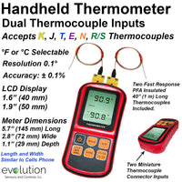
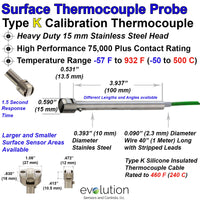
Thermocouple Connectors ensure the Temperature measurement signal (millivolts) from the thermocouple sensor or lead wire is accurately transmitted to the display or control Instrumentation.
The 3 Things you should know in selecting the correct thermocouple connector.
1 - Thermocouple Alloys - the thermocouple pins/contacts within the connector must match those in the thermocouple sensor and or lead wires. This seems very basic, although I have seen well established organizations make this mistake and experience the resulting temperature measurement challenges..
-
9 Different pairings of Thermocouple Alloys are used in the primary thermocouple connectors. It is common for these alloy pairs to be referred as Calibrations and use letters to designate the type of thermocouple.
- J, K, T, E, and N calibrations represent the most commonly used designs, sometimes referred as Base Metal Thermocouples. Type C, R/S, U (B) thermocouples are utilized in much more specific, and many times higher temperature ranges or applications.
2 - Color Coding - this system is used to help identify and match the connectors to the thermocouple wire and sensors. This color coded system can be Confusing and there are several specific important points to understand in this methodology.
- The USA (ANSI) color coding for thermocouple connectors and wire is Different than the IEC (International Electrotechnical Commission) and other individual country color codes.
- The IEC (International Electrotechnical Commission) color code is fairly easy to understand with the Thermocouple Connector color matching both the outer insulating jacket of a thermocouple pair and the insulation of the positive wire. For example the IEC color code for the very popular Type K calibration has a Green thermocouple connector body and Green insulation on the wire.
- The USA (ANSI) has several Exceptions to matching the color of the connector to wire. The insulation color on the individual positive wire will match the connector body, with the exception of Type J calibration.
- A significant Difference in the USA color code is Thermocouple Grade wire has a Brown colored outside insulated jacket for the popular K, J, T, E and N calibrations wire pairs. The Connector colors are K -Yellow, J -Black, T- Blue, E- Purple and N-Orange.
- The USA insulation colors on thermocouple Extension Grade wire will match the connector body colors.
- We understand Thermocouple Color Codes can be confusing and provided a chart along with other technical reference in this document and throughout the Evolution Sensors website.
3 - Functional Temperature - the capabilities of the thermocouple connector body material and the thermocouple alloy pins is a Critical selection point to consider in your temperature measurement application.
- The metal alloy pins within the thermocouple connector can be capable of operating temperatures from Below Zero to above 2,000F.
-
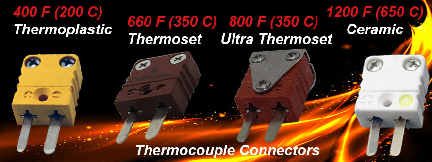
The materials used to make connector body are key factor in determining the Functional temperature range of thermocouple connector.
-
These materials are typically Thermoplastics, Thermosets or Ceramics providing an overall range from - 40 F to 1200 F (-40 C to 650 C). Each material provides specific temperature range and mechanical capabilities along with cost considerations.
Read more →


