A RTD is a Temperature Sensor with an excellent reputation for accuracy, repeatability and Temperature Range of -320 to 1562°F (-196 to 850°C)
The sensor is based on Resistance Temperature Detector technology, meaning a change in temperature results in measurable resistance change in the sensor output.
RTD's typically have been viewed as being the Second Most Utilized Temperature Sensor throughout industry. Thermocouples are thought to be most utilized temperature sensor design, although RTD's appear to be growing at a faster rate. In fact we have noted an increasing amount of automation industry and equipment builders choosing a RTD sensor design as their Primary Temperature Sensor Solution.
Historically accuracy has been the primary key factor in choosing an RTD over other tempeature sensors although professionals from industy have stated several other factors. These include "easily interfaces with my newer electronic controls", "a higher level of immunity from electrical interference", " the delivery time and pricing has improved" and "a direct drop-in replacement without recalibrating my control and monitoring signals on existing equipment and or next generation designs."
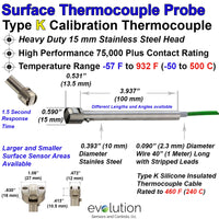
If you are considering RTD's as your primary choice or an alternate design to your existing temperature sensor technology please review the content below. We start with a basic visual outline of a RTD Probe Construction and the components associated with this technology. Beyond this image we have provided a step by step outline of the sensor components, the options and how these components or construction influence the performance of the RTD.

The RTD Sensing Element itself is the core temperature measurement technology of a RTD probe, and can have a maximum temperature range of approximately -320 F to 1,562 F (-196 to 850 C).

(Additional details on the RTD Elements can be found by clicking on the image above)
The actual Temperature Operating Range and Overall Performance of a RTD probe or sensor assembly is significantly Influenced by the Components and Construction surrounding and or connecting to the RTD sensing element. The key components/construction are as follows.
- The Outside Sheath, Metal Tube or Sensor Housing
- The Insulation on and or around the Connection Lead Wire
- The Wiring, Connections and Connectors
Outside Sheath, Metal Tube or Sensor Housing - These sheaths typically consist of a metal tube, or a machined metal housing. At times plastic housings or coverings are selected for specific applications.
- A Stainless-Steel tube or machined housing provides the Highest Temperature range and mechanical diversity
- Aluminum, Brass and Copper designs can enhance the Heat Transfer performance and or reduce costs.
- Plastic and Polymers materials provide solutions for lower temperature and or improved Resistance to Corrosion.


The Insulation on or around the Connected Lead Wire to the RTD sensing element or within the protective sheath is a key factor influencing the temperature and related performance capabilities of the sensors.
- RTD Sensors and Probes - with a PFA or FEP Teflon-like 400 to 500 F (200 to 260 C) rated lead wire encased in a metal tube, protective housing or an exposed element tend to be Most Utilized Design due to the ability to provide solutions for many diverse applications.


- MI Cable RTD Probes - are made with a metal sheath/tube (typically Stainless Steel) with compacted high temperature Mineral Insulation inside the tube providing insulation surrounding the bare nickel connecting wire. This design provides the opportunity to utilize the RTD Sensing element throughout its Full Temperature Range along providing a high level of mechanical durability.


- RTD Probes and Sensors - with Internal or External Fiberglass Insulated Connected Lead Wire along with ceramic cement protection of the element lead wire can provide up to 900 F (500 C) Plus temperature range range. The mechanical and heat transfer performance of this design can be enhanced with a backfill of alumina or Mgo mineral insulation.


RTD Wiring, Connections and Connectors - RTD sensor and probes are commonly offered with a 2, 3, or 4 Wire Construction. The selection of the circuit design is typically influenced by the accuracy desired, along with need to match the design inputs of the measurement display and or control instrumentation.
(The images below have links to product web pages with 2, 3, or 4 wire leads)
- 2 Wire RTD - the resistance in 2 leads wires cannot be eliminated, and in consideration to this factor the design is typically utilized in combination a short length of lead wire and where less accuracy is required.

- 3 Wire RTD - is the Most Common configuration utilized throughout many industries and applications. The 3rd wire provides a method to remove the lead wire average resistance resulting in good accuracy despite wire lengths.

- 4 Wire RTD - provides the opportunity to determine and remove the actual resistance of the 4 lead wire from the circuit. This design results in excellent accuracy and historically was used in laboratories, the utilization of this design is Growing in Industrial Applications especially with the use of M12 style - 4 Pin Circular Connectors

- RTD's with Stripped Wire Lead Connections - nickel or silver plated stranded copper wire with Stripped Leads is one of the most common connection methods from the RTD probe assembly to the electronic display and control instrumentation.These strip leads can be enhanced with spade lugs or wire ferrules.
- RTD Connectors - 2 and 3 pin male Quick Connect Designs are especially popular for testing application with multiple sensors and control panels. Innovations with a 4 pin M12 Circular Style Connector has provided excellent solutions for applications where a connection can be compact and secure from vibration, wash down and or other environment conditions.
- RTD Connection Heads - industrial applications in petrochemical, power generation, metals processing, bio-pharmaceutical and other will use Connection Heads made from Aluminum, Cast Iron, Stainless Steel and Plastics to protect the transition from the RTD sensor to the connection. These heads also provide opportunities for electronic transmitter and signal conditioning at the sensor location.
(The images below are examples of RTD's with different connections and product web page links.)


Click here to see the full selection of RTD products from Evolution Sensors
RTD Sensitivity - an RTD is a temperature sensitive resistance device, as such an indication of sensitivity is the amount the resistance changes as temperature changes
- The sensitivity and accuracy of the RTD Probes are influenced by core factors such as the Temperature Coefficient of Resistance (TCR) and the Resistance of the Circuit itself from the RTD Element.The TCR indicates the average resistance change of the sensor per degree °C over the range of 0°C to 100°C.
- The TCR of 0.00385 is the IEC (International Electrotechnical Commission) standard with Platinum and is the by far the most utilized TCR throughout industrial and commercial RTD temperature measurement.
- Increased sensitivity is achieved through higher resistance circuits and or a higher TCR.
- For example RTD probes with a TCR of 0.00385 have a100 ohm platinum element and will have a 0.385 Resistance Change for each 1°C change. A 1000 ohm platinum is 10 times More Sensitive and will have 3.850 ohm change
- A 100 ohm nickel element has a TCR of 0.00618 and is 1.6 times more sensitive than 100 ohm platinum RTD
- A sensor with higher sensitivity is not necessarily more accurate. The increase sensitivity does provide a larger signal and this will be less susceptible to lead-wire effects and electrical noise. A larger resistance also mitigate self-heating effects in the sensor element.
- RTD Accuracy/Tolerance - efforts are ongoing to further define accuracy ranges of RTD probes and the elements although many industry professionals are familiar the 4 accuracy classes and temperature ranges of Class B, Class A, 1/3 DIN and 1/10 DIN.
- Class A and Class B are the most Commonly Recognized and Utilized Accuracy and for closer tolerances within a much narrower temperature range 1/3 DIN and 1/10 DIN.