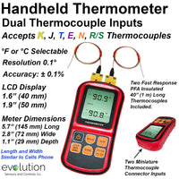
Thermocouple Connectors ensure the Temperature measurement signal (millivolts) from the thermocouple sensor or lead wire is accurately transmitted to the display or control Instrumentation.
1 - Thermocouple Alloys - the thermocouple pins/contacts within the connector must match those in the thermocouple sensor and or lead wires. This seems very basic, although I have seen well established organizations make this mistake and experience the resulting temperature measurement challenges..
- 9 Different pairings of Thermocouple Alloys are used in the primary thermocouple connectors. It is common for these alloy pairs to be referred as Calibrations and use letters to designate the type of thermocouple.
- J, K, T, E, and N calibrations represent the most commonly used designs, sometimes referred as Base Metal Thermocouples. Type C, R/S, U (B) thermocouples are utilized in much more specific, and many times higher temperature ranges or applications.
2 - Color Coding - this system is used to help identify and match the connectors to the thermocouple wire and sensors. This color coded system can be Confusing and there are several specific important points to understand in this methodology.
- The USA (ANSI) color coding for thermocouple connectors and wire is Different than the IEC (International Electrotechnical Commission) and other individual country color codes.
- The IEC (International Electrotechnical Commission) color code is fairly easy to understand with the Thermocouple Connector color matching both the outer insulating jacket of a thermocouple pair and the insulation of the positive wire. For example the IEC color code for the very popular Type K calibration has a Green thermocouple connector body and Green insulation on the wire.
- The USA (ANSI) has several Exceptions to matching the color of the connector to wire. The insulation color on the individual positive wire will match the connector body, with the exception of Type J calibration.
- A significant Difference in the USA color code is Thermocouple Grade wire has a Brown colored outside insulated jacket for the popular K, J, T, E and N calibrations wire pairs. The Connector colors are K -Yellow, J -Black, T- Blue, E- Purple and N-Orange.
- The USA insulation colors on thermocouple Extension Grade wire will match the connector body colors.
- We understand Thermocouple Color Codes can be confusing and provided a chart along with other technical reference in this document and throughout the Evolution Sensors website.
3 - Functional Temperature - the capabilities of the thermocouple connector body material and the thermocouple alloy pins is a Critical selection point to consider in your temperature measurement application.
- The metal alloy pins within the thermocouple connector can be capable of operating temperatures from Below Zero to above 2,000F.
- The materials used to make connector body are key factor in determining the Functional temperature range of thermocouple connector.
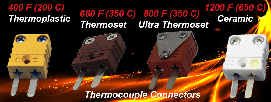
- These materials are typically Thermoplastics, Thermosets or Ceramics providing an overall range from - 40 F to 1200 F (-40 C to 650 C). Each material provides specific temperature range and mechanical capabilities along with cost considerations.
The images below show connector made with different materials in the popular miniature male connector configuration. Click on the images for additional details.


The Most Utilized thermocouple connectors are made from Thermoplastics. They have a temperature range of approximately -40 to 400°F plus (-40 to 200°C) and have a good level of mechanical durability.
Connectors made from Thermoset materials are an excellent choice where the connector itself would be exposed to a continuous 500°F to 800°F (260°F to 425°C) range. Some connectors made from thermosets can crack more readily then the thermoplastic connector design, although the thermoset has a higher level of impact resistance as compared to ceramics.
The Thermoset Connectors from Evolution Sensors are available in a High Temperature Design with capabilities up to a continuous 660°F (350°C) and the Ultra High Temperature design can operate at 800°F (425°C) continuously with intermittent temperature capabilities to 1000°F (540°C).
The Highest Temperatures thermocouple connectors are made from Ceramics with capabilities in the -20 to 1200 °F (-29 to 650 °C) range. Ceramic connectors also provide the opportunity to be utilized in Vacuum applications since the material has been fired in high temperature kilns and the potential of outgassing or contamination has been virtually eliminated. Ceramic connectors are more susceptible to mechanical damage as compared to thermoplastic or thermoset designs.
The Size and Shape of connectors is another important factor in your selection process, for the most part connectors are typically rectangular or circular shaped. The primarily available in a Miniature body design or a larger Standard body design.
The rectangular Miniature Connector Design utilizes Flat Pins. The circular miniature designs are primarily made with small round pins, although at least one manufacturer in the industry has also introduced a circular design with flat thermocouple alloy pins. The Standard Size Connector contains Round Pins. Beyond these choices your next step is to determine the connector construction from a form and fit perspective for your application.


- The most widely used connector construction is the Quick Connect - Disconnect designs, these are the flat rectangular body designs.The male version of this connector tends to have a 2.5 to 1 volume of utilization as compared to the female. This is due to the male typically being connected to the sensor and subject to higher temperatures and harsher conditions than the female.
- Circuit Board designs provide the opportunity to directly solder on the connector onto the printed circuit boards in a flat, side or rear mounted orientation.
- Panel mount connector designs are typically utilized in coordination with a control panel for process or test equipment is involved and it is important to provide an organized and fast connection or disconnection at the panel.
- Circular and Multi-Pin designs with threaded bodies or flanges provide higher performance in applications with vibration, wash-down processes and other environmental conditions, or they simply are used to eliminate accidental disconnection. They also provide the the opportunity for multiple connections in one connector body.


- 2-Pin Connectors are the Most Popular and utilized with a single circuit temperature sensor design.
- 3-Pin design (1 pin is copper ground) is selected at times to help reduce electrical signal interference in thermocouples
- The 3 pin design with all copper pins is popular with single circuit 3-wire RTD temperature sensing applications.
- 4-Pin design is sometimes referred to as a Dual Connector and is utilized for 2 thermocouple circuits.
- A 4 pin design is also used with a single circuit 4-wire RTD temperature sensors.
- Multi-Pin designs can provide from connection opportunities from 1 temperature measurement circuit along with communication circuits or as many as 24 temperature circuits with or without other signal connections.
- The pins within K, J, T, E and N thermocouple connector are made from and Match the Thermocouple Sensor Alloys.
- The pins for the higher temperature precious metals and special materials thermocouple such R, S, B and C thermocouples are made from a set of Specially Matched Alloys.

- ANSI (American Nation Standards Institute) a good example of this color code format is the very popular Type K thermocouple connector is identified with a Yellow body. Connectors with Higher Temperature materials utilize a Yellow dot or the letter K printed on the body or related hardware.
- IEC (International Electrotechnical Commission) effectively consolidated several European country codes into one. The popular Type K thermocouple connector is identified by a Green color marking.
- The Japanese Color Code is also utilized with some regularity and the popular Type K is Blue.
- Prior to the IEC efforts to consolidate the color code Historic Engineering documentation will show further variations in the color code from various countries.