A RTD Element is the Core Temperature Sensing Technology utilized in RTD probes and sensor assemblies. The sensing element is based on Resistance Temperature Detector technology, meaning a change in temperature results in a measurable and consistent resistance change.
Click for RTD Elements available from Evolution Sensors
In a previous article we indicated RTD's are typically viewed as being the second most utilized temperature sensor technology throughout industry. Despite being second, some estimates indicate the utilization of RTD Sensors is Growing at Twice the Rate of thermocouples.
What is influencing this growth rate? Some of factors include easier compatibility with newer electronics and interchangeability with other RTD sensors. The acceptance of the Thin Film RTD Element design is one of most significant driving factors. We have seen an increase in Performance Capabilities, a Decrease in Cost and more Availability of these devices.
The investment and increased utilization of advanced Semiconductor and Electronic Component Processes in the development and manufacturing of the thin film RTD sensing elements has significant enhanced the sensors performance.

The technology of these elements have earned an excellent reputation of Accuracy and Repeatability for themselves as well for RTD probes assemblies. Depending on the design selected the elements can provide excellent performance in the temperature range of -320 F to 1,562 F (-196 to 850 C) along with some speciality designs reaching 1,832 F (1,000 C)
In most temperature measurement applications the RTD Element is encased in a protective tube or housing with extended insulated wire leads, or connectors transferring the temperature signal to instrumentation. This sensor assembly is called a RTD probe, a basic construction outline is diagrammed below.
(RTD Probes and Sensors are referenced in this article in a very basic manner to assist in the explanation of RTD elements. If additional insight on the RTD probe assemblies is desired please click on the RTD Construction image below.)

An Exposed RTD element is utilized in some applications, providing faster response times and smaller profile where space is limited. Below are images and product page links showing examples of this design.Appropriate care must taken to ensure the RTD element is not damaged.


RTD sensors rely on a consistent and repeatable resistance measurement to provide accurate temperature performance and with this in mind the Resistance Circuit of the RTD element is made from either Platinum, Nickel or Copper, and in some cases Nickel-Iron (Balco) or other materials.
These materials are deposited with thin film semiconductor like processes or in a wire coil form. They are made in a very precise manner to provide the appropriate and repeatable resistance through the temperature range. The most commonly utilized material to create to resistance circuit is Platinum due its overall performance.
- Platinum provides the best linear resistance change resulting in excellent accuracy.
- The platinum design is highly repeatable over a wide temperature range.
- Advances in manufacturing technology has made the platinum material a cost-effective design.

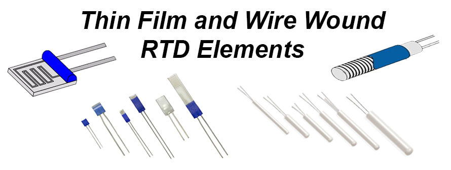
- RTD Element Mechanical Construction – there are 3 primary mechanical configurations. Thin Film and Wire Wound are primarily constructions utilized in RTD probes. The details of these 2 designs are outlined below. The 3rd mechanical construction is an electronic component type design for circuit board mounting. The electronic design is not included in this discussion.

- A Thin Film Design is a small flat ceramic-like chip with an extremely thin-film of platinum or nickel deposited on the surface of the chip. Lead wires are made from platinum coated nickel, palladium gold or nickel and bonded to the circuit.
- The thin film design is made with semiconductor-like technology in several thousand-piece batch quantities resulting in a significantly reduced cost per element while maintaining consistent performance. The Manufacturing Technology improvements for this design has been a significant factor with the Increased Market Utilization of RTD sensor and probes.

- Wire Wound Designs are a small tube-like construction made from ceramic or glass with very small diameter platinum wire coiled on or within a ceramic or glass core with palladium gold alloy wire.
- The wire wound design provides a Wide Temperature Range and High Accuracy across this range. This design has much higher materials and labor cost as compared to the thin film elements.
RTD Element Sensitivity - an RTD is a temperature sensitive resistance device, as such an indication of sensitivity is the amount the resistance changes as temperature changes
- The sensitivity and accuracy of the RTD elements are influenced by core factors such as the Temperature Coefficient of Resistance (TCR) and the Resistance of the Circuit itself. The TCR indicates the average resistance change of the sensor per degree °C over the range of 0°C to 100°C.
- A TCR of 0.00385 is the IEC (International Electrotechnical Commission) standard with Platinum and is the by far the most utilized TCR throughout industrial and commercial RTD temperature measurement.
- A TCR of 0.003916 is a standard established by the USA and Japan in 1981 and is not utilized at anywhere near the level of acceptance with the IEC standard 0.00385 TCR
- A TCR of 0.003926 is the ITS-90 Lab Standard and requires platinum with a purity equal to or greater than 99.999%. The platinum wire must be wound in a strain-free configuration.
- The Circuit Resistance in a RTD elements are available in 100, 200, 500, 1000 and 2000 ohm designs. The 100 ohm is the Most Popular design
- Increased sensitivity is achieved through higher resistance circuits and or a higher TCR.
- For example platinum elements have a TCR of 0.00385 a 100 ohm platinum element will have a 0.385 Resistance Change for each 1°C change. A 1000 ohm platinum is 10 times More Sensitive and will have 3.850 ohm change
- A 100 ohm nickel element has a TCR of 0.00618 and is 1.6 times more sensitive than 100 ohm platinum RTD
- A sensor with higher sensitivity is not necessarily more accurate. The increase sensitivity does provide a larger signal and this will be less susceptible to lead-wire effects and electrical noise. A larger resistance also mitigates self-heating effects in the sensor element.
- RTD Element Accuracy/Tolerance - efforts are ongoing to further define accuracy ranges between thin film and wire wound RTD elements although many industry professionals are familiar the 4 accuracy classes and temperature ranges of Class B, Class A, 1/3 DIN and 1/10 DIN.
- Class A and Class B are the most Commonly Recognized and Utilized Accuracy and for closer tolerances within a much narrower temperature range 1/3 DIN and 1/10 DIN.

Jim Ferguson, the author of this information and founder of Evolution Sensors and Controls lead the development, manufacturing and technical support of thin film RTD elements earlier in his Temperature Measurement Technology career.